
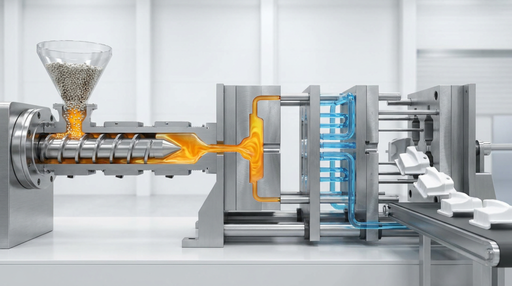
The four stages of injection molding are: (1) Injection — molten plastic fills the closed mold cavity under high pressure; (2) Packing — additional pressure compensates for material shrinkage; (3) Cooling — the plastic solidifies as heat is removed; (4) Ejection — the mold opens and finished parts are pushed out by ejector pins. This cycle repeats every 10–60 seconds.
Further Reading
For neutral technical background, see injection molding background.
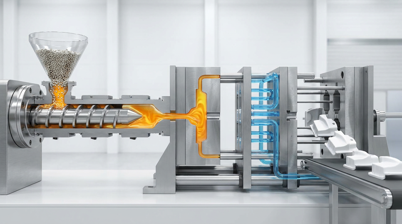
Stage 1: Injection — Filling the Mold
The injection stage begins when the reciprocating screw moves forward like a plunger, pushing molten plastic from the barrel through the nozzle, into the sprue, along the runner channels, through the gates, and finally into the mold cavity.
| Parameter | Typical Range | Effect on Part Quality |
|---|---|---|
| Injection speed | 50–500 mm/s | Too slow: freeze-off, short shot • Too fast: flash, burn marks |
| Injection pressure | 500–2,000 bar | Insufficient: short shot • Excessive: flash, residual stress |
| Fill time | 0.5–5 seconds | Faster fill reduces cycle time but increases shear heating |
| Transfer point | 95–98% full cavity | Too early: short shot • Too late: flash and overpacking |
Key principle: Injection stops at approximately 95–98% cavity fill. The final 2–5% is completed during the packing stage. This “transfer point” from injection to packing is one of the most critical process parameters in injection molding.
Stage 2: Packing (Holding) — Compensating for Shrinkage
After the cavity is filled, the process transitions to the packing (or holding) phase. The screw continues to apply lower, controlled pressure to push additional material into the cavity as the plastic begins to cool and shrink.
- Pack pressure: Typically 50–80% of peak injection pressure
- Pack time: 2–15 seconds, determined by gate freeze-off time
- Insufficient packing: Sink marks, internal voids, underweight parts, dimensional variation
- Excessive packing: Flash near gate, high residual stress, part sticking, difficult ejection
- Gate freeze test: Weigh parts at increasing pack times until weight stabilizes — that point is the minimum effective pack time
Stage 3: Cooling — Solidifying the Part
Cooling begins simultaneously with packing and continues after pack pressure is released. Cold water (or temperature-controlled fluid) circulates through channels machined into the mold, extracting heat from the part until it is rigid enough to be ejected without distortion.
| Factor | Detail | Impact |
|---|---|---|
| Cooling time | 5–40 seconds | 60–70% of total cycle time — the dominant variable |
| Mold temperature | 20–60°C (amorphous) • 60–120°C (semi-crystalline) | Affects crystallinity, surface finish, warpage |
| Coolant temperature | 10–40°C water | Lower temp = faster cooling but risk of condensation |
| Cooling channel design | 1.5× diameter from cavity surface | Poor design = hot spots, sink marks, warpage |
| Conformal cooling | 3D-printed channels following part contour | 20–40% cycle time reduction in complex molds |
Stage 4: Ejection — Removing the Finished Part
When the part has cooled sufficiently below its heat deflection temperature (HDT), the mold opens and the ejector system activates to push the part out of the cavity.
- Ejector pins: Most common method. Hardened steel pins push against the B-side (non-cosmetic) surface. Pin marks are visible and must be positioned in non-cosmetic areas
- Stripper plate: A moving plate strips the part off the core — used for thin-wall containers and tubular parts where pin marks are unacceptable
- Air assist: Compressed air injected into the cavity helps release parts from deep cores or low-draft surfaces
- Robot removal: High-volume production uses robotic arms to remove, orient, and place parts on conveyors or into inspection stations
- Early ejection risk: Ejecting before HDT causes warpage, surface deformation, and dimensional non-conformance
Complete Cycle Time Breakdown
| Stage | Duration | % of Cycle | Key Optimization |
|---|---|---|---|
| Mold close | 1–3s | 5% | Optimize clamp speed profile |
| Injection (fill) | 0.5–5s | 5% | Increase speed within flash limit |
| Packing | 2–15s | 15% | Minimize to gate freeze-off point |
| Cooling | 5–40s | 65% | Primary optimization target |
| Mold open | 1–3s | 5% | Fast-open profile |
| Ejection | 0.5–2s | 5% | Automate with robot |
Frequently Asked Questions
What is the most important stage of injection molding?
Cooling is the most important stage for productivity because it accounts for 60–70% of total cycle time. However, the injection and packing stages have the greatest influence on part quality — defects like sink marks, weld lines, and dimensional variation are primarily set during these stages.
What happens between injection and packing?
The transition from injection to packing is called the “transfer point.” At this point, control switches from velocity (injection) to pressure (packing). The transfer typically occurs when the cavity is 95–98% full, detected by screw position, cavity pressure sensor, or time.
Can the four stages overlap?
Yes. Cooling begins as soon as molten plastic contacts the mold wall — before the cavity is even full. Packing and cooling overlap significantly. Only injection and ejection are truly sequential and non-overlapping.
Why does cooling take so long?
Plastic is a very poor thermal conductor — approximately 1,000 times worse than steel. Heat must diffuse slowly from the plastic through the mold wall to the coolant. Reducing wall thickness and improving cooling channel placement are the primary ways to reduce cooling time.
Need a Mold with Optimized Cycle Time?
BuildMold engineers design cooling circuits for minimum cycle time. Free DFM review and quotation within 24 hours — send us your 3D file.