
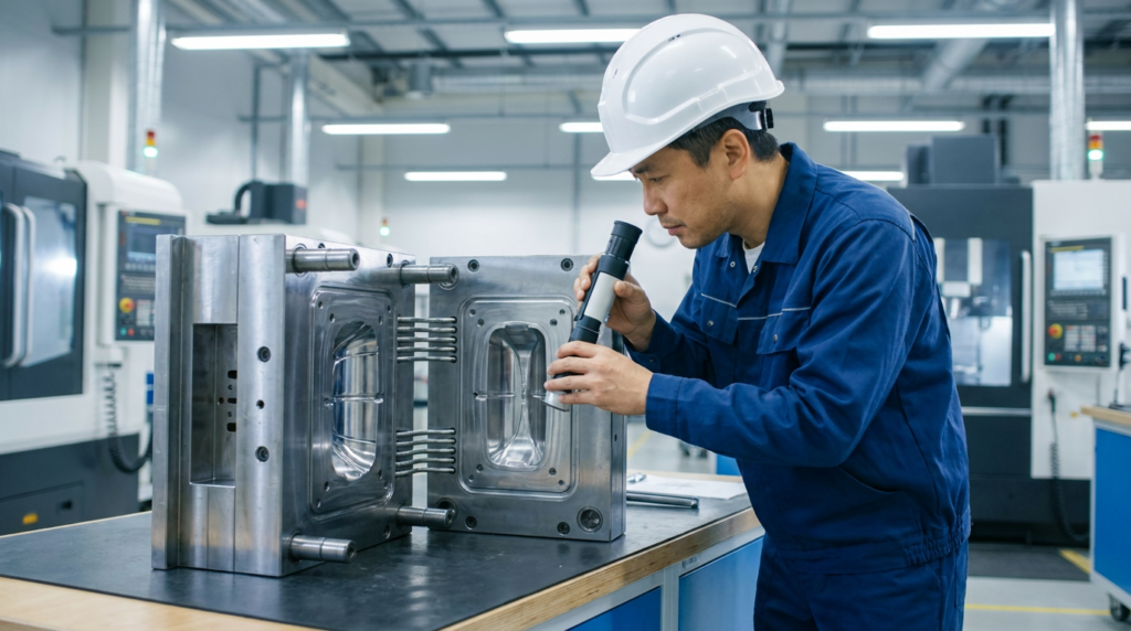
📌 Key Takeaways
- Steel grade selection (P20, H13, S136) directly impacts mold lifespan and part quality
- DFM analysis before steel cutting eliminates costly rework — draft angle, wall thickness, and gate location are critical
- 5-axis CNC + Mirror EDM achieves cavity tolerances of ±0.002mm
- Cooling system design controls up to 70% of cycle time
- Structured T1–T3 mold trials with CMM validation ensure production readiness
Plastic injection molding is one of the most widely used manufacturing processes for producing high-volume, high-precision plastic components. At its core, the quality and performance of every molded part depend directly on the design and craftsmanship of the injection mold itself. This article provides a technical overview of key considerations in injection mold manufacturing — from material selection and DFM analysis to cooling system design and mold trial validation.
Further Reading
For neutral technical background, see injection molding background.
Also see How Do You Choose the Right Mold Steel? for steel grade selection by resin, production volume, wear, corrosion, and surface finish.
1. Mold Steel Selection
Choosing the right steel grade is the foundation of a durable, high-performance mold. The selection depends on production volume, part material, and surface finish requirements:
| Steel Grade | Hardness | Best For | Typical Shot Life |
|---|---|---|---|
| P20 (1.2311) | 28–32 HRC | General-purpose, medium volume | < 500,000 |
| 718H (1.2738) | 33–38 HRC | Large mold bases, thick sections | 500,000–800,000 |
| NAK80 | 37–43 HRC | Mirror finish, optical & cosmetic parts | 500,000+ |
| H13 (1.2344) | 48–52 HRC | High-temp resins (PC, PA+GF), high volume | 1,000,000+ |
| S136 (1.2083) | 48–52 HRC | Corrosive resins, medical, food-contact | 1,000,000+ |
2. Design for Manufacturability (DFM) Analysis
Before cutting steel, a thorough DFM review identifies potential molding defects and reduces costly design iterations. Key DFM checkpoints include:
- Draft angle — A minimum draft of 0.5°–1° per side is required on all vertical walls. Textured surfaces typically require 3°–5° to allow clean part ejection without drag marks.
- Wall thickness uniformity — Abrupt thickness transitions cause sink marks and warpage. Recommended wall thickness for most thermoplastics is 1.5–3.5mm, with transitions not exceeding a 3:1 ratio.
- Undercuts — Internal or external undercuts require lifters, sliders, or collapsible cores, adding complexity and cost. DFM aims to minimize or redesign these features where possible.
- Gate location — Gate position affects fill pattern, weld line placement, and cosmetic appearance. For multi-cavity molds, balanced gating is essential to ensure uniform fill across all cavities.
- Parting line — The parting line must be strategically placed to avoid witness lines on critical surfaces and to facilitate venting and ejection.
3. Cavity & Core Machining
Dimensional accuracy in cavity and core machining directly determines part dimensional compliance. BuildMold’s machining workflow follows a structured sequence:
| Process | Equipment | Tolerance | Application |
|---|---|---|---|
| Rough CNC milling | 3-axis CNC | ±0.05mm | Bulk material removal |
| Finish milling | 5-axis CNC | ±0.005mm | Complex contoured surfaces |
| Mirror EDM | Sodick / Makino | ±0.002mm, Ra0.2μm | Fine details, sharp corners |
| Wire-cut EDM | Slow-wire machine | ±0.002mm | Inserts, sliders, lifters |
| Surface grinding | Surface grinder | 0.002mm/300mm | Parting surface flatness |
4. Cooling System Design
The cooling system accounts for approximately 70% of the injection molding cycle time. An optimized cooling circuit directly improves productivity and part quality:
- Cooling channel diameter — Standard diameter is 8–12mm, positioned 1.5x diameter from the cavity surface for uniform heat extraction.
- Conformal cooling — For complex geometries, conformal cooling channels follow the part contour, reducing hot spots and cycle time by 20–40%.
- Baffle and bubbler inserts — Used in deep cores and ribs where straight-through channels are not feasible.
- Mold temperature control — Water temperature is typically maintained at 20–60°C for standard resins; higher temperatures (80–120°C) are used for crystalline materials like POM and PA to improve surface finish and reduce internal stress.
5. Mold Trial & Validation
A structured mold trial process ensures the mold performs to specification before mass production:
- T1 trial (first shot) — Validates basic mold function: filling, venting, ejection, and cooling. Focus is on identifying flash, short shots, burn marks, and sink marks.
- T2 trial — Process parameters are optimized (injection speed, pressure, temperature, cooling time). Dimensional measurement of critical features against the 2D drawing.
- T3 / FAI (First Article Inspection) — Full dimensional report using CMM (±0.001mm accuracy). Part appearance, gate vestige, and weld line position evaluated against customer specifications.
- Mold acceptance — Mold is accepted when parts consistently meet dimensional tolerances, surface finish requirements, and functional performance criteria across a minimum sample run (typically 30–100 shots).
Conclusion
High-quality injection mold manufacturing is a multi-disciplinary engineering process that requires precision at every stage — from DFM analysis and steel selection to machining, cooling design, and trial validation. At BuildMold, each mold is engineered with production efficiency and long-term durability in mind, backed by ISO 9001:2015 quality management and a team of 50+ experienced tooling engineers.
🔗 Related Articles
Have a Mold Project in Mind?
Our engineering team provides free DFM review and quotation within 24 hours. Send us your 3D file or drawing to get started.