
📌 Key Takeaways
- 5-axis CNC machining achieves cavity tolerances of ±0.003mm in a single setup — eliminating repositioning errors that accumulate with 3-axis machines
- Carbide end mills with TiAlN coating are the standard for hard mold steel (48–62 HRC) — HSS tools wear too quickly above 45 HRC
- High-speed machining (HSM) at 20,000–40,000 RPM with light cuts reduces cutting forces and extends tool life by 3–5×
- Surface finish from CNC alone reaches Ra0.8–1.6μm; EDM and polishing are required to reach Ra0.2μm and below
- CNC and EDM are complementary — CNC removes bulk material, EDM achieves fine details and surfaces inaccessible to rotating tools
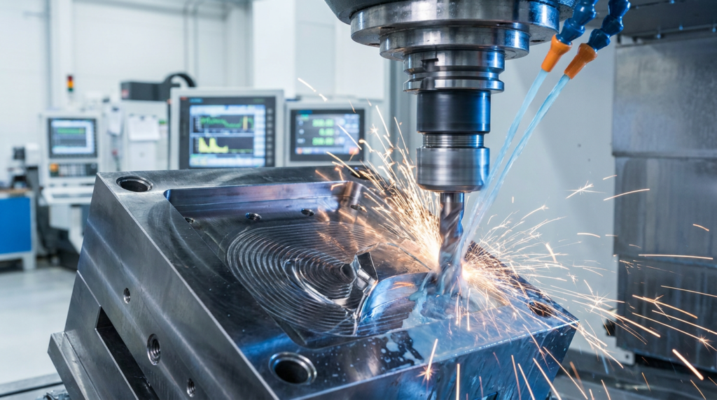
CNC (Computer Numerical Control) machining is the primary manufacturing process for creating the cavities, cores, and structural components of injection molds and stamping dies. Modern multi-axis CNC machining centers can machine complex 3D surfaces with micron-level accuracy — capabilities that define the quality and repeatability of every part the mold produces. This guide covers how CNC machining is applied in mold manufacturing, from roughing to finishing, and how it integrates with EDM for complete mold production.
Further Reading
For neutral technical background, see CNC machining background.
1. Role of CNC Machining in Mold Manufacturing
CNC machining performs two distinct roles in mold production: bulk material removal (roughing) and precision surface generation (finishing). The choice of 3-axis versus 5-axis equipment determines which features can be machined in a single setup and what tolerances are achievable.
| Capability | 3-Axis CNC | 5-Axis CNC |
|---|---|---|
| Simultaneous axes | X, Y, Z | X, Y, Z + A, B (or C) |
| Typical tolerance | ±0.01–0.02mm | ±0.003–0.005mm |
| Setups required | Multiple (repositioning) | Single setup for complex geometry |
| Surface finish (Ra) | Ra1.6–3.2μm | Ra0.8–1.6μm |
| Best for | Flat features, pockets, holes | Contoured surfaces, undercuts, compound angles |
| Repositioning error | Accumulates with each setup | Eliminated (single datum) |
2. 5-Axis CNC: Why It Matters for Complex Molds
For complex mold geometries — swept surfaces, angled shut-offs, deep cores with contoured walls — 5-axis CNC is not a luxury but a necessity. The ability to tilt and rotate the workpiece (or the spindle) relative to the cutting tool allows the machine to maintain optimal cutting geometry at every point on the surface, dramatically improving both accuracy and surface quality.
- Single-setup accuracy — All features machined from one datum reference, eliminating cumulative repositioning errors that can reach ±0.05mm on 3-axis machines with multiple setups.
- Shorter cutting tools — The ability to tilt the workpiece allows use of shorter, stiffer cutters, reducing tool deflection and chatter. This directly improves surface finish and dimensional accuracy.
- Undercut features — Side cores, angled parting surfaces, and geometry on the back of a part can be machined without additional fixtures or EDM in many cases.
- Cycle time reduction — 5-axis HSM (High-Speed Machining) at 20,000–40,000 RPM with light radial engagement achieves material removal rates 2–3× faster than conventional 3-axis milling of the same features.
3. Cutting Tools & Parameters for Tool Steel
Machining hardened mold steel (P20 at 32 HRC, H13 at 50 HRC) requires specialized tooling and carefully calculated cutting parameters. Using the wrong tool or cutting too aggressively causes rapid tool wear, poor surface finish, and thermally induced residual stress in the mold steel.
| Material | Tool Type | Coating | Cutting Speed (m/min) | Feed per Tooth (mm) |
|---|---|---|---|---|
| P20 / 718H (28–38 HRC) | Solid carbide end mill | TiAlN | 80–150 | 0.05–0.12 |
| H13 (48–52 HRC) | Solid carbide, 4-flute | AlCrN | 40–80 | 0.02–0.06 |
| SKD11 / D2 (58–62 HRC) | CBN insert or carbide | AlTiN | 20–50 | 0.01–0.03 |
| Graphite (EDM electrode) | Solid carbide, 2-flute | Uncoated or diamond | 200–500 | 0.05–0.15 |
4. Tolerances & Surface Finish Achievable
CNC machining alone cannot achieve the finest surface finishes required for optical or high-gloss mold cavities. Understanding the limits of each process helps engineers design the right machining sequence.
| Process Stage | Dimensional Tolerance | Surface Finish (Ra) |
|---|---|---|
| Rough CNC milling | ±0.05mm | Ra 3.2–6.3μm |
| Semi-finish CNC | ±0.01–0.02mm | Ra 1.6–3.2μm |
| Finish CNC (5-axis HSM) | ±0.003–0.005mm | Ra 0.8–1.6μm |
| Mirror EDM (after CNC) | ±0.002mm | Ra 0.2–0.4μm |
| Manual polishing | No stock removal | Ra 0.01–0.05μm (mirror) |
5. CNC vs EDM: When to Use Which
CNC and EDM are complementary processes in mold manufacturing — each excels where the other has limitations. Understanding when to switch from CNC to EDM is essential for efficient mold production.
| Criteria | CNC Machining | EDM (Sinker / Wire-cut) |
|---|---|---|
| Material hardness limit | Up to ~65 HRC (CBN tools) | No hardness limit |
| Sharp internal corners | Limited by tool radius | Achieves R0.1mm or sharper |
| Deep narrow slots | Difficult (tool deflection) | Wire-cut excels |
| Material removal rate | High (bulk removal) | Low (slow process) |
| Surface finish | Ra 0.8μm (finish pass) | Ra 0.2μm (mirror EDM) |
| Best application | Open surfaces, pockets, contours | Textures, fine details, hardened inserts |
Conclusion
CNC machining — particularly 5-axis high-speed machining — is the backbone of modern mold manufacturing. It delivers the dimensional accuracy, surface quality, and production speed that high-precision tooling demands. At BuildMold, our machining floor operates 5-axis CNC centers, Mirror EDM, and Wire-cut EDM in an integrated workflow, ensuring every mold component meets its dimensional specifications before assembly.
🔗 Related Articles
Need Precision Mold Components?
Send us your 3D drawings and our CNC team will provide a free machining feasibility review and quotation within 24 hours.
Or email us directly: sales@buildmold.com